![]()
| When handling the sensor it appears to
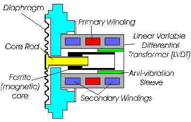
rattle? For enhanced vibration immunity, an anti-vibration sleeve is now supplied as standard in all sensors. This sleeve contains 'side to side' movement of the ferrite core preventing any stresses that may be otherwise applied to the diaphragm / core rod attachment weld by excess movement. It should be noted that tapping the body of the sensor, especially low range units (0.5m to 2m), a mechanical knocking may be heard. This is normal and is not, therefore, a cause for concern. |
 |
Can I shorten my sensor cable?
During the calibration of the instrument the sensor is 'tuned' or matched to the electronics module. Shortening the cable can have a detrimental effect on the calibration. It is, therefore, preferable to loosely coil any excess cable (minimum coil diameter 12"/300mm). Where this is not convenient, the instrument may be returned for recalibration with a shorter length.
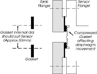
| I have a sensor with a DN25 flange, when
I tighten the sensor to the tank the transmitter output
fluctuates Although the flange is a DN25, the clearance hole is somewhat larger to accommodate the diameter of the diaphragm. In some cases, dependant upon the gasket type used, it can have a tendency to extrude, when compressed, to such an extent that it interferes with the diaphragm. In these cases it will be necessary to increase the centre hole through the gasket to match the sensor (approx 37mm diameter). Care should be taken to tighten the mounting bolts evenly. Tightening one bolt to the maximum extent and fully compressing the gasket / seal in the process will almost certainly result in a stress being built up when the opposing bolt is tightened. This can cause an initial calibration shift but, potentially worse, make the unit susceptible to temperature change which can cause an unpredictable change in the output. |
 |
My sensor diaphragm is dented, will this affect it's performance?
It is likely that a zero offset (high) will result. If this can be corrected using the zero adjustment in the amplifier to give 4.00 mA when the tank is empty the unit should still function although there may be linearity errors.
Serious denting of the diaphragm. will result in an offset which cannot be adjusted out and the sensor will need returning to PSM for repair / replacement. click here for details
There is liquid in the electronics housing, what could this be?
The sensor is vented to atmosphere through the integral cable into the electronics housing, and via a sintered filter in the centre cable gland. Although weatherproof to IP65 when mounted in the correct orientation with the glands on the underside, should there be any flooding or excess of water through hosing down, there may be an ingress of moisture. Excessive changes in humidity in the atmosphere may also cause condensation within the housing. It is important in these cases to ensure the venting is directed away from this environment to avoid any blockage occurring within the integral vent tube. This is achieved by removing the sintered filter and replacing with 6mm od tube and run to a dry area.
If it is evident that the liquid has not entered via the housing or it's glands the likely cause is damage to the sensor diaphragm, and / or sensor cable for submersible units - usually the sensor will be beyond repair and will need returning to PSM for repair / replacement. click here for details. Extreme caution is necessary for tanks which may contain aggressive and harmful substances.
Can I change the cable glands on the electronics housing?
Where possible it should be ensured that weatherproof sealing is maintained. Also, in intrinsically safe applications, the BASEEFA certification will be compromised if the originally supplied glands are replaced - PSM can offer replacement housings with glands up to PG16 for the signal cable if required.
Can I change the orientation of the sensor mounting?
If the zero plane is not altered the orientation of the sensor should have little or no effect on the calibration of the unit unless it is low range, this may be compensated for using the zero adjustment within the electronics housing.
I have an externally mountable electronic sensor, can this be submersed?
Providing the sensor has a 'booted' cable gland assembly at the rear it is fully submersible to IP68
In an intrinsically safe environment what can be mounted in the hazardous area?
Both the sensor and the amplifier module may be in the hazardous area (sensor zone 0 amplifier zone 1) The 4 to 20mA output loop must be protected using an approved zener barrier which must be in the safe area and connected to an approved IS earth.
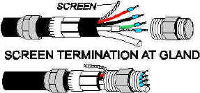
| How should the instrument be earthed? The complete instrument (ie both amplifier and sensor) should be earthed at one point only. This prevents possible induced voltages and errors of measurement which might occur if the screen were connected to earth at two points which had different potentials with respect to each other. The normal practice is to use 2 core screened cable for the 4-20mA signal loop, and to connect the cable's screen to the power supply earth. This screen then terminates in the amplifier module's gland, which is specifically designed for the purpose. The sensor cable also uses a similar gland and the cable is likewise terminated. The GRP housing features a special metallic / conductive coating inside to ensure earth continuity and, when correctly sealed, protects against RFI. Note that the sensor cable outer screen is NOT internally connected to the sensor metalwork. This is in accordance with the I.S. regulations, as it would otherwise mean the tank structure was connected to (and compromising) the IS earth |
 |
In order to pass the 600 series capillary through a wall can I disconnect the sensor?
The capillary is filled with an inert gas but it is not pressurised, therefore, if the sensor is detached from the capillary it should be reattached in the minimum possible time to avoid gas escaping and any moisture entering.
One of my RT168 amplifier modules has failed, can I substitute with an existing spare?
Yes you may substitute the RT168 however, during the calibration of the instrument the sensor is 'tuned' or matched to the electronics module. A different module will have different characteristics which will affect the calibration. It is, therefore, preferable to return the instrument for 'matching' of the sensor to the new RT168. Alternatively, if practical, calibration can be checked and adjusted by varying the level in the tank. Normally, output should be 4mA for tank empty and 20mA for tank full, however, this depends on the display instrument. For example, a PSM Minder series display will carry the final calibration data, in this case the output will be calibrated 4 to 20mA over the nominal range of the transmitter. Compare the physical tank depth and fluid S.G. with the label on the instrument to see if the set range = tank depth x SG. If not , the display equipment is correcting the signal, and the output will be 20mA at tank full. Under such conditions, if test equipment and pressure sources are not available, it is simpler to adjust the zero with the tank known to be empty, then adjust the span such that the display reads full when the tank is known to be full. This assumes the display equipment is functioning correctly
My level transmitter does not appear to be working - what should I check for?
Check supply voltage - measured directly across the +ve and -ve terminals of the amplifier. The voltage should be between 12 and 24Vdc. Less than 12V can cause loop 'starvation' meaning the transmitter is unable to develop it's full 20mA output causing an error of display.
Check current output - With the tank empty (or sensor removed from tank) check the output current by connecting a multi-meter to the test pins in the amplifier which are marked for this purpose. The output should be 4mA. If it is slightly off, the zero adjustment in the bottom right hand corner of the amplifier can be used to adjust it.
If there is no output or a fixed output - Assuming visual inspection reveals no obvious mechanical damage to the sensor or amplifier, disconnect the sensor cable from the amplifier and measure the following resistance values:
- Between black and red conductors should be 1100 ohms
- Between green and screen should be 56 ohms
- There should be no circuit between the sensor cables' overall screen and any of the 4 conductors
Short or open circuits, or resistances more than 15% off the above values indicate and internal sensor fault caused by, either contamination, or electrical overload. The sensor is an all welded assembly and must be returned to PSM for repair.
My instrument is working but does not appear accurate, what could the reasons for this be?
- Is the instrument installed on it's intended application?
- Does the calibrated range on the units label correspond with the actual tank size and the S.G. of the liquid in the tank?
- Are the sensor and transmitter a matched pair? - check they both have the same serial No
If any of the above are found to be incorrect, provided no attempt at adjustment has already been made, it is recommended that the units are substituted for the correct / matched duties, and / or partner component. If adjustments have been made, full recalibration is required.
Before suspecting the units calibration always validate the display system / indicator to ensure that this is correct. If a signal generator is available, applying a 4 to 20mA in place of the transmitter's signal will enable the display equipment to be checked.
I have a 600 Tankwatch series which shows a constant error - can I adjust the pointer?
Where there is a constant error in the reading, ie. the pointer is always 5o below where it should be, it is possible to move the pointer position. Access is gained by removing the indicator bezel by rotating it approximately 1/4 turn anti-clockwise. Lift the bezel, glass and seal off.
The pointer is a push fit on the spindle and can be removed by pulling it directly away from the mechanism. Extreme care should be taken to avoid bending this spindle. The pointer may then be repositioned and pressed back onto the spindle by hand only. Once the correct position is achieved the bezel, glass and seal may be replaced using a reversal of the removal procedure.
I have adjusted the zero pot on the RT168 and now the range is inaccurate?
Having adjusted the zero pot the overall calibrated span will have altered, the sensor will need to be pressurised to full range and the span pot adjusted to 20mA accordingly to compensate.
You will be invoiced for the replacement unit initially, but subject to investigation of the faulty unit, credit will be issued against the invoice. please ensure you follow our returns procedure for a speedy solution
My cable appears to be melting is this due to temperature?
The upper temperature limits on the cable is 150 deg C, possibly a more likely cause is a chemical reaction with the process medium.
If I need to return my instrument do I have to return both the sensor and the Electronics?
It is preferable, the sensor and electronics module are a 'matched pair' please ensure you follow our returns procedure for a speedy solution
Our instrument has been damaged, do you offer a repair service?
Yes. You will need to return the unit to us along with appropriate documentation please click here for instructions.
PLEASE NOTE: Many of our products are used for arduous duties in chemicals which are hazardous to health. For H&S we need you to certify that the product has been appropriately cleaned or that the product is not hazardous to health)
On receipt we can then carry out an inspection to evaluate whether to repair or replace returned item.
Do you have a local Agent who can attend site?
PSM provides both an installation and commissioning service for newly supplied items at competitive rates, and can also visit site to support customers requests for after sales assistance. Please contact us or email service@psm-sensors.co.uk
We want to change the duty of our sensor to a new tank?
First we need to establish the specification of the instrument. Each instrument supplied is manufactured and calibrated to specification application requirements.
The original instrument range will have been selected based on required measuring range, and will be limited by its ‘Nominal’ range. If the new tank falls within 30 to 100% of Nominal span, then it would be OK after the necessary calibration adjustment.
We need to lengthen the cable from 3 to 12 Metres,
can we do this?
The same principles apply to lengthening cable as to shortening. During the calibration of the instrument the sensor is 'tuned' or matched to the electronics module. Lengthening the cable can have a detrimental effect on the calibration. Also, because the cable has an integral vent tube special attention needs to be taken over the location and type of connector used to ensure that no moisture can contaminate instrument vent tube. Any moisture ingress will prevent the unit from seeing "atmospheric pressure" and adversely affect performance, over time it can also cause complete failure by accumulating within the sensor. We can provide a suitable connector and additional cable where required but as previously mentioned the unit may require recalibrating.
Yes, but please bear in mind that any changes made by non PSM Personnel will invalidate the product Guarantee, and are also likely to invalidate I.S. BASEEFA approval.
We have a problem with our Minder, is keeps displaying PU16,17,18,19 then Error 91
Error 91 is a data read fail error and may have been caused by power spike - You can reset by pressing the SP and Alarm button simultaneously during the power up cycle.
It is recommended that you recheck configuration data after this error message as this may have been corrupted and all will require re-entering.
|
|
Power up Mode & enter Calibrate ModeOn initial power up both LEDs illuminate for approximately 5 to 45 seconds whilst unit validates its signal. Both will also illuminate when the magnetic key is held to either Z or S targets to confirm unit has entered Calibrate Mode.
|
|
|
Normal
Operation
Following power up mode this indicates a valid echo is being received and unit is functioning normally. Where, in normal operation, there is a sudden step change in the echo distance the unit will automatically go to Validate Mode. When it establishes that the new echo is valid the signal output will change accordingly and the LEDs will return to Normal Operation status.
|
|
|
Invalid Range
This indicates that a valid echo is being received but that the distance it represents is outside of the calibration limits which have been set for the unit. If this distance is known to be valid the unit can be recalibrated to accept this new distance.
|
|
|
Calibrate Mode / Validate ModeWhen calibrate mode is entered and the magnetic key is removed from the Z or S target both LEDs will flash for approximately 5 to 45 seconds while the unit verifies the echo. Assuming echo is verified the LEDs go to Normal Operation status. Note that when the magnetic key is held against the Z or S targets to set calibration the signal will immediately go to 4.00 mA or 20 mA as appropriate.
|
|
|
No Echo / Echo
Loss
When,
after Power Up
mode no echo can be found for approximately 1 minute LED 2 will illuminate
red indicating calibration cannot be undertaken. Also, where echo is lost
in normal operation, the output signal initially freezes its value. If,
after approximately 1 minute of searching a valid echo is not found the
output signal goes to the fault condition level set for it and L2
goes to red.
|
|
|
|
|
![]()