|
Benefits at a glance
Non-contact radar measurement
4-20mA output
Choice of antenna types
Hart, Modbus, Profibus interface options
Accurate to 5mm on ranges up to 30 metres with 2mm
repeatability
9.9GHz Quartz controlled all digital processing
PLL- stabilised FMCW X-band antenna.
|
|
PSM can now offer RADAR level gauges to provide the
very best accuracy for the monitoring of storage & process tanks in both
the industrial & marine sector.
This all new gauge utilises the very latest in
FMCW technology developed from the Military sector to offer non-invasive
measurement of level at a competitive price.
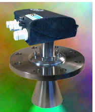
The iRT is a cost effective level sensor
designed for continuous non-contact level measurement
The primary head unit is mounted to a standard
tank flange fitting. and can be removed under service conditions.
For long-distance transmission of level data,
various standard communication interfaces (4 to 20mA, HART, MODBUS, PROFIBUS)
are available for connection to plant control systems.
The primary head can also accept up to 4
additional 4-20mA input signals, for example from temperature and/or pressure
transmitters. These are then retransmitted via the chosen digital output.
Communications
Various output standards are available to suit
application requirements HART
MODBUS PROFIBUS
|
Specification |
|
|
System
structure |
|
|
Operating mode |
Quartz-controlled dynamic PLL-stabilised
FMCW radar in the X band (8.5 – 9.9 GHz) with digital signal
processing; compact & modular design |
|
Measured quantities |
Primary quantity: distance; derived
quantities: level, volume |
|
Measuring range |
Maximum measuring range: 30 m (100 ft) |
|
Blocking distance |
Minimum 0.2 to 0.5 m (0.65 to 1.6 ft), |
|
Rate of change in level |
£ 10 m/min (£ 33 ft/min) |
|
Measured product
conditions
|
|
Physical properties |
Generally the product should have a
relative permitivity of 3 or greater (er < 3) For er
³ 1.5 the product is still well recommended with application profiling. |
|
Process temperature |
Unrestricted but be aware of ambient and
flange temperatures |
|
Operating pressure |
Cone antenna: -1 to +10 bar. |
|
|
|
|
Component parts |
|
Housing options |
Epoxy coated cast aluminium. Optional—
Stainless Steel DIN 1.4581 and ANSI 316 Ti. |
|
|
Flange system and antenna |
Stainless Steel 1.4435 (316 L) / PTFE |
|
|
Gaskets |
FFKM (Kalrez 4079); Kalrez 2035; Viton
(FPM); PTFE is also in contact with the product in all versions |
|
|
Process connection |
|
|
|
Cone antenna |
BS 4504-3.3:1989, BS1560-3.1:1989
ANSI B 16.5 |
DN 50 to DN 200, PN 6 to PN 64;
2” to 8”, 150/300 lb/RF |
|
Rod antenna |
Refer to separate data sheet |
|
|
Electrical connections |
Cable entries: M 25 x 1.5
Terminals: 0.5 – 2.5 mm2
(solid conductor: max. 4 mm2 ) |
|
|
Ambient conditions |
|
Hazardous locations |
BASEFA EEx d IIB T4, Zone 0, 1, 2
(EN50014, EN50018 Europe) - Pending |
|
Type Approval |
Lloyds Register - Pending |
|
EMC |
By design, EN 50081-1 Conducted and EN
50082-2 Radiated. |
|
Protection category EN60529/IEC529 |
IP 67 to DIN 40050 / IEC 144 |
|
Shock resistance |
Impact test to EN 61010, Sect. 8.2 with
0.5 J energy; drop test to prEN 50178 |
|
Vibration endurance limit |
By design, IEC 68-2-6 and prEN 50178
(10-57Hz: 0.075mm / 57-150Hz: 1g) and possibly 1mm amplitude at 2-13.2
Hz / 0.7g acceleration at 13.2-100Hz |
|
Salt spray test |
3 week duration |
|
Ambient temperature at signal transducer |
Cone antenna: –20°C to +55°C (-24°F
to +131°F)
Functional range: -40 °C to +170°C
(-40°F to +158°F) |
|
Flange temperature |
Cone antenna (T ambient £ 50°C
(122°F)): -20°C to +150°C (-22°F to +284°F) |
|
Climate |
Optional integral 10 watt electronics
heater element. |
|
Operator interface |
|
Operator interface language |
English |
|
Units of measurement |
Lengths: m, cm, mm, inch, ft, %,
Volume: m3 , Litre, US Gal, GB
Gal, ft3, bbl, %
Conversion unit: any text
|
|
Power supply |
|
24V ACDC |
Standard: 18 – 31.2 V DC or 18 – 26.4
V AC (47-63 Hz) |
|
Universal (115/230 V AC) |
Optional: 100-240 V AC (tolerance: 85-264
V AC); 47-63 Hz |
|
Power consumption |
Typically 8.9W / 12.2VA |
|
Current inputs |
Additional inputs may be multiplexed
meaning fewer cables are required on the vessel's deck. |
|
Type |
4 x Current input, active or passive |
|
Current range |
0(4)-20mA |
|
Accuracy/linearity |
0.5% (rel. 20 mA; 25°C/77°F) |
|
Temperature drift |
£ 300 ppm/K (typically 70 ppm/K) |
|
Load |
50 W (current), 10 kW (voltage) |
| Relay
output |
|
Switching output (optional) |
Nominal switching capacity
(resistive load): 1 A 30 VDC, 0.3 A 125 VAC; On resistance £ 20 W;
floating |
| Failure
signal |
|
Current output |
error signal: 2 mA (Exi = 3.6 mA) |
|
Switching contact |
contact opens or closes |
|
Digital interfaces |
error flags |
| Measuring
accuracy |
|
Error of measurement |
max. +/- 5mm (+/- 0.2”) or 0.1% |
|
Repeatability |
£ 0.5 x error of measurement |
|
Measured-value resolution |
1 mm (0.04”) |
|
|
|
|