|
|

|
![]()
![]()
![]()
![]()
![]()
![]()
![]()
![]()
![]()
coming soon....
Integrated Support System for the iCT range of Level and Pressure Transmitters.

|
Integrated Support System |
Key FeaturesIn digital mode, any transmitter can be accurately rearranged from any point on the RS485 network without the need to physically access it to apply pressure. During factory calibration, a table is generated that uniquely characterises each iCT over its full pressure range. This table is compensated for the effects of temperature, non-linearity and hysteresis, and is stored in the transmitter’s non-volatile memory. Unlike conventional analogue transmitters where the 4-20mA output is dependant on the sensor’s displacement, it is possible to assign the 4 and 20mA points anywhere on this table. The user simple enters the pressure values at which 4mA and 20mA outputs are required and accurate recalibration is complete. The iCT incorporates a 12-bit ADC feedback circuit which constantly monitors the 4-20mA loop. The micro-controller compares its value with the digital signal and the user set calibration and ensures that it is accurate. If, under fault conditions, measurement errors are beyond dynamic correction, an error message is transmitted to the digital output. In addition, the 4-20mA current output may be driven to a pre-determined fixed value. This option is user selectable, as is the actual current value within the limits 3 to 22.5mA. In digital mode the transmitter also provides a temperature measurement accurate to within one degree centigrade. For tank volume or any other applications requiring linearisation, iCT can be programmed with a 20-point look-up table, providing a direct output in volumetric rather than level terms. All configuration information in the iCT is stored in non-volatile re-programmable memory and while in set-up mode all of it’s monitoring activities are suspended.
|
|
|
Connecting ISSISS uses the RS485 industrial serial communications standard. Using ¼ node drivers up to 128 transmitters may be connected on a single screened twisted pair cable, which can be up to 1500 meters long. ISS can be connected to any point on the RS485 data loop. The iCT’s optional interface module has provision for local temporary connection of a laptop and for more permanent installations terminals are provided to run the RS485 cable to the central PC. Connection to the PC takes full advantage of the latest Universal Serial Bus (USB) standard. PSM provide a low cost module that converts the RS485 signal to USB standard, this plugs directly into any USB port and has three terminals for connection of the RS485 data cable (A, B & Screen). The USB port can also power the iCT directly from the PC, and two further terminals (+ / -) are provided for this. Based on current USB specifications, the extremely low power requirement of the iCT when operated in digital mode means the PC can power an entire loop of 128 transmitters. Even when the iCT is operated in both analogue and digital modes, up to 10 can still be driven direct from the PC. ICT Interface moduleThe optional interface module provides a convenient means of cable termination for both the analogue and digital outputs of the iCT. It has two termination blocks for the RS485 loop, allowing a single two core screened cable to be looped from one transmitter to the next. The two termination blocks are internally hard-wired across for loop integrity, ensuring failure of one sensor does not result in drop-out of the entire loop. Terminals are also provided for the iCT four-core cable, and the 4-20mA output signal. Using ISSISS has several modes of operation. Firstly as a configuration and commissioning tool, secondly as a dignostic tool for troubleshooting, and finally as an on-line monitoring device, which collects data from transmitters I service and can display the information or pass it to other PC resident applications. ISS is fully Windows OLE compliant, meaning any other OLE compliant Windows application can exchange information with ISS as a background operation. ISS operates just like any other Windows application and as such will be immediately familiar. It is a Multi-Document Interface, meaning specific areas are open within their own dedicated window. When executed, ISS will automatically check the USB port to determine if one or more iCT’s are connected. If any are detected, it will interrogate them and gather all of their stored parameters. These are then saved on the PC against each iCT’s unique serial number and may be displayed in a dedicated window. If no iCT’s are detected, or the user requests it, the ISS will switch to off-line mode. Off-line enables a file to be created, which contains the required configuration settings for specific transmitters. In this way it is possible to pre-define and save the required settings for an entire installation of transmitters without being at the location. To implement these settings, the user would connect to any point on the RS485 network and download the settings to all units. Configuration
Commands In
set-up mode the user may amend the following parameters: Node
address- this
is set for each transmitter before its installation into a multi-drop RS485
network. ISS detection of a single transmitter (i.e ‘local’ mode on the
termination enclosure) ignores the node address. Two identical node addresses
will be indicated as an error by the ISS. During commissioning, the ISS will
sequentially address a possible total 128 nodes and present information
regarding respondents, nulls and conflicts. Manual or automatic re-ordering of
the node addresses can then be invoked. Transmitter
calibrated range
and zero / span settings – entered in engineering units. Current loop scaling – the 4-20mA output may be assigned over all or any portion of the calibrated range, the zero may be offset or suppressed and the output may be inverted (i.e. 20-4mA). Tank
profile table – this
provides a 20-point “look-up” table to correct for a non-linear tank
shape. The points may be taken directly from a sounding table and are entered
as a comparison of tank height against tank volume. Test on
demand – instructs
the iCT perform a Built In Test (BIT) and send result. Forced
span- this
enables the user to set a “deadband” around the maximum span so that the
4-20mA output is forced to 20mA when the actual level is within a selectable
percentage value of the full span. The % values for above and below full span
are independently adjustable. Forced
zero – this
provides the same functionality as the forced span settings. Specific
gravity – entered
as an actual value. This is used as an active scaling parameter, to correct
the 4-20 output. Rate of change (leak)
detection for both pressure and temperature
– there are two parameters to set. Firstly, the time is set (in one hour
increments), over which the change is to be monitored. Secondly, the
acceptable % change limit is set. If the change is greater than the limit set,
an error message will be transmitted when the transmitter is polled (in
multi-drop mode) or periodically in single transmitter mode.
Set
operational mode – selects
digital only mode, analogue only mode, or digital and analogue mode. Diagnostic
Mode
ISS
provides a number of “tools” to assist an engineer in the initial
commissioning or subsequent fault-finding of an iCT or equipment connected to
it. Force
analogue output – to
4, 12, or 20mA, irrespective of applied pressure, for proving connected
instrumentation. Read
maximum and minimum temperature the unit has been subjected to – programmable
in degrees centigrade, Fahrenheit, or Kelvin. Read maximum hydrostatic pressure and vacuum the unit had been subjected to – in selected Engineering Units. BIT
failure code / Error messages – the
iCT can generate up to 256 error messages defining a variety of failures /
conditions. In the case of multiple conditions, the first byte sent in error
message sub-package indicates the number of error bytes to follow. Operational ModeThe
following read-only information is available Date of manufacture – format DD-MM-YY Unit
serial number – an eight or nine digit code
which uniquely identifies the iCT. Customer ID – free format field for customer advised detail, for example tank name. Calibrated Range – in engineering units. Total operational time – incremented hourly. Factory set calibration parameters – these are presented as a ‘look-up’ matrix, in tabular form. Node address Serial number – unique to the transmitter Current pressure – in selected units of measure Current temperature – in selected engineering units Error messages - The operational modes available depend upon the supply voltage supplied. Foe a supply voltage between 6-12 v DC, the transmitter operates in digital-only mode. Above 12 V, to a maximum of 32 V, the analogue output may also be enabled for use, as well as, or instead of, digital operation. |
|
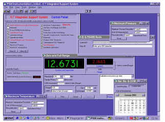 The
Integrated Support System (ISS) is a PC based software application, which runs
in the windows environment. Working together with the micro-controller
embedded in the iCT range of Level & Pressure transmitters, it provides an
unparalleled range of data and functionality, allowing the user to simply and
precisely tailor transmitters for their intended duty. In normal operation the
iCT’s are continually monitored for correct operation and routing of their
output to other PC based applications.
The
Integrated Support System (ISS) is a PC based software application, which runs
in the windows environment. Working together with the micro-controller
embedded in the iCT range of Level & Pressure transmitters, it provides an
unparalleled range of data and functionality, allowing the user to simply and
precisely tailor transmitters for their intended duty. In normal operation the
iCT’s are continually monitored for correct operation and routing of their
output to other PC based applications.